In silico QLSI
PhaseLAB enables not only to process QLSI interferograms, it also possesses a numerical simulation part. PhaseLAB can simulate the electromagnetic field at the image plane of a microscope, for a given object at the sample plane, and extract from it the theoretical intensity and wavefront images.
Moreover, it can also model the interferogram of this exact same object, and process this modelled interferogram as it it were a real experimental one.
This modality of PhaseLAB, called in Silico QLSI, enables the easy screening of parameters such as the wavelength, the grating pitch, the grating-camera distance, the dexel size, etc, and their effects on the image quality (signal to noise ratio, accuracy, artefacts, etc), without conduting any experiment.
This modality of PhaseLAB was introduced in Ref. 1 and widely used in Ref. 2.
Model a nanoparticle
The simplest object that can be modelled in Silico is a nanoparticle, or more precisely a dipole. Here is a code that models a microscope, and a dipole corresponding to a 100-nm gold nanoparticle placed on glass and immersed in water:
 1%% code that simulates the image of a gold nanoparticle
 2
 3lambda = 530e-9;            % Illumination wavelength
 4Npx = 300;                  % Final image with Npx*Npx pixels
 5Mobj = 100                  % Objective magnification
 6NA = 1.0                    % Objective numerical aperture
 7
 8radius = 60e-9;             % Nanoparticle radius
 9
10% model the setup
11ME = Medium('water', 'glass');
12OB = Objective(Mobj,NA,'Olympus');
13CGcam = CGcamera('sC8-944');
14MI = Microscope(OB,'Olympus',CGcam);
15IL = Illumination(lambda,ME);
16
17% model the nanoparticle
18DI = Dipole('Au',radius);   % creation of the Dipole object
19DI = DI.shine(IL);          % illumination of the dipole
20
21% compute the images
22IM0 = imaging(DI,IL,MI,Npx);
23
24% display the images
25IM0.figure                  % display the images in the GUI

In line 16, the dipole is illuminated. It means that the polarisation vector of the dipole is calculated, and assigned to the object property DI.p:
>> DI.p

ans =

    1.0e-30 *

    -0.7697 + 0.4309i   0.0000 + 0.0000i   0.0000 + 0.0000i
This dipole needs to be calculated before the imaging() function is called (line 19).
In line 19, the electromagnetic field is calculated using the imaging function (see The imaging function section.) The first input is the Dipole object, the second is the Illumination object, the third the Microscope object and the last one, Npx, is the number of pixels (rows and columns) of the final (square) image. The function returns the electromagnetic field at the image plane of the microscope as an ImageEM object.
Model an interferogram
PhaseLAB can not only simulate the electromagnetic field at the image plane of a microscope, it can also simulate an interferogram, by incorporating a QLSI grating in the model. This modification can be calculated using the CGMinSilico function. Here is the synthax:
Itf = CGMinSilico(IM0,'shotNoise',true);
The keyword 'shotNoise' adds the natural shot noise of the selected camera specified in the Microscope object MI. Other Name-value inputs can be specified. For more information, refer to The CGMinSilico function.
Process the interferogram
Finally the interferogram can be processed as if it were an experimental interferogram using the QLSIprocess method:
IM = QLSIprocess(Itf,IL);

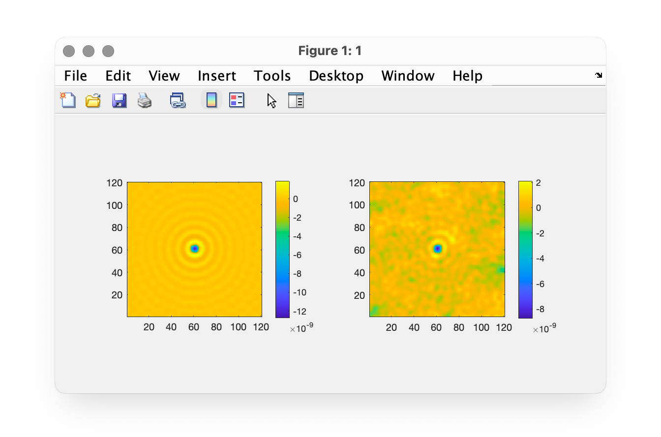
dynamicFigure('gb', IM0, 'gb', IM)
Here is the displayed figure, comparing the theoretical OPD image, and the OPD image measured with the sC8 camera from Phasics, including the camera shot noise.
Model arbitrary objects
Objects of arbitrary geometry (big spheres, rods, biological cell, …) can also be modelled using the in Silico algorithm. For this purpose, PhaseLAB should be coupled with the IFDDA toolbox, as done in Ref. .. [#QPIcomparison].
- 1
Cross-grating phase microscopy (CGM): In silico experiment (insilex) algorithm, noise and accuracy, B. Marthy, G. Baffou, Opt. Commun. 521, 128577 (2022)
- 2
Quantitative phase microscopies: accuracy comparison, P.Chaumet, P. Bon, G. Maire, A. Sentenac, G. Baffou, Light: Science & Applications, accepted (2024)